Viewing ITM Trace Output without an IDE
Viewing ITM Trace Output without an IDE
TL;DR
-
Start openocd
-
Open a telnet session to the openocd server on port 4444
-
Configure the ITM and set the port to 0 with this command:
stm32f4x.tpiu configure -protocol uart -traceclk 180000000 -output :3344 -formatter off -
Enable the ITM with this command:
stm32f4x.tpiu enable -
Open a second terminal and run
nc localhost 3344to view the output. This is where your ITM messages will be printed. -
You have to halt and restart the target for settings to take effect using this command in the telnet 4444 session:
reset halt resume -
Your target will run after the resume command and you should see the ITM messages in the 3344 connection.
What is ITM?
The ITM (Instrumentation Trace Macrocell) is part of the Cortex-M debug infrastructure. It’s like a serial port baked into the CPU, letting you send data (e.g., strings or variables) to a debug tool via the SWO pin. No UART, no extra pins—just your SWD setup and some configuration magic. You can read about it on the ARM website.
When using something like an STM32 Nucleo or Discovery board the SWO pin is usually connected to the ST-Link already and messages are send via the ST-Link USB connection to openocd. While STM32CubeIDE has a built-in console for viewing ITM messages, you may find yourself in an environment where you want to view the ITM messages without using an IDE. Perhaps a continous integration system or a custom setup. In this post, we will look at how to do that.
Setting up the ITM
If you are using CMSIS headers, which you should be, for your project you can use the ITM_SendChar function to send a character to the ITM. This function is defined in core_cm4.h (or similar) and is part of the CMSIS library.
In the picture below you can see the ITM_SendChar also takes care of enabling the ITM and setting up port 0 for output. Additionally you’ll notice that the function exists in all cores except the Cortex-M0 and M0+.
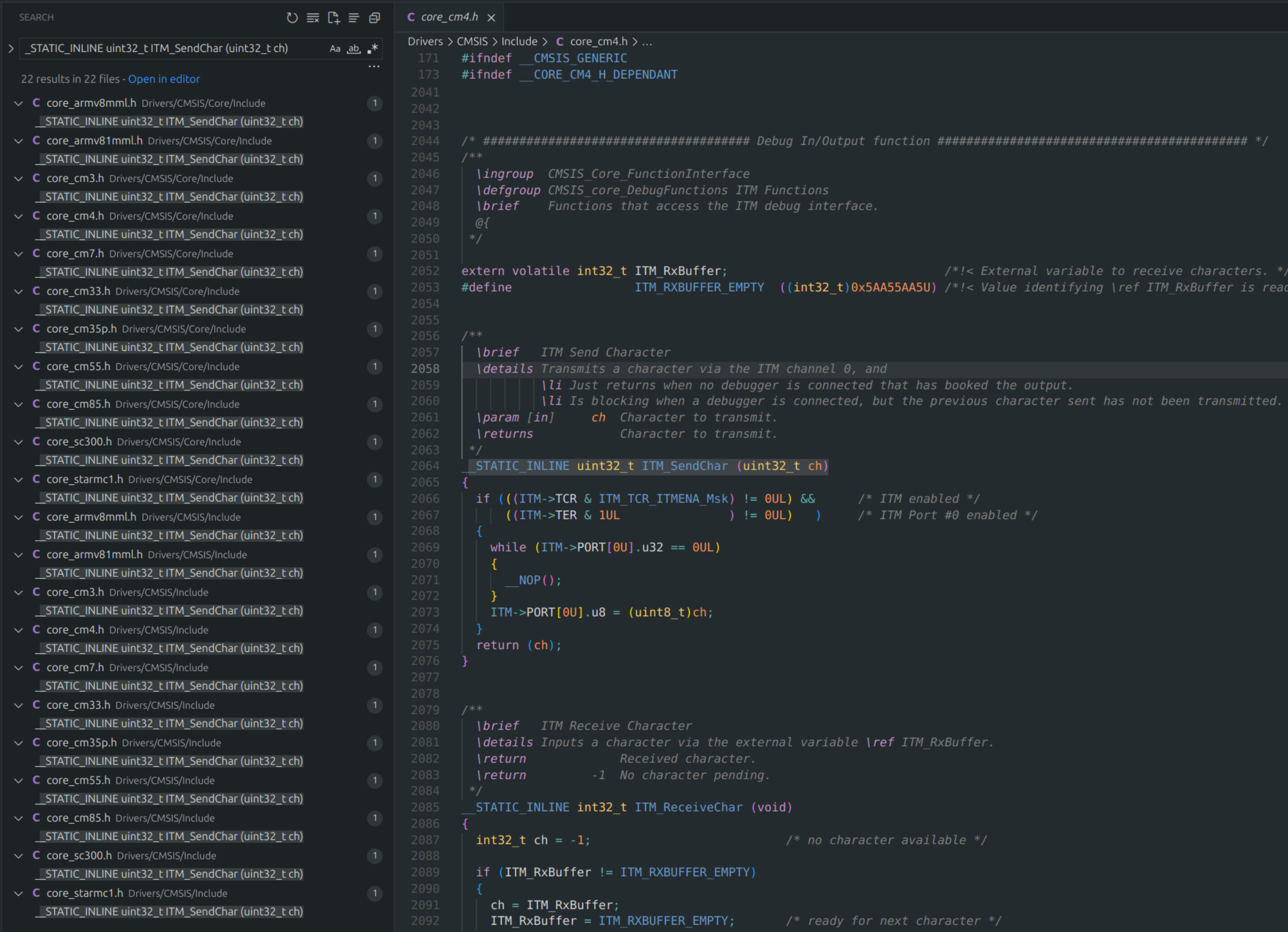
A quick look at the function shows that it checks if the ITM is enabled and if port 0 is enabled. If both are true, it waits until the ITM port is ready to send data and then sends the character. The function is defined as follows:
/**
  \brief   ITM Send Character
  \details Transmits a character via the ITM channel 0, and
           \li Just returns when no debugger is connected that has booked the output.
           \li Is blocking when a debugger is connected, but the previous character sent has not been transmitted.
  \param [in]     ch  Character to transmit.
  \returns            Character to transmit.
 */
__STATIC_INLINE uint32_t ITM_SendChar (uint32_t ch)
{
  if (((ITM->TCR & ITM_TCR_ITMENA_Msk) != 0UL) &&      /* ITM enabled */
      ((ITM->TER & 1UL               ) != 0UL)   )     /* ITM Port #0 enabled */
  {
    while (ITM->PORT[0U].u32 == 0UL)
    {
      __NOP();
    }
    ITM->PORT[0U].u8 = (uint8_t)ch;
  }
  return (ch);
}
It becomes clear that there is some slight overhead and it is blocking when the port is not ready. However the raw data throughput is very high (higher than UART in most cases). And no UART peripheral is needed. This article is not a pitch for you to start using ITM so we can leave it at that for now.
Setting up an OpenOCD script
Normally you will call your openocd like this:
openocd -s path/to/scripts/folder -f interface/stlink-dap.cfg -f target/stm32f4x.cfg
I want to point out something in thestm32f4.cfg openocd script. Below is a snippet of the script:
# SPDX-License-Identifier: GPL-2.0-or-later

# script for stm32f4x family

#
# stm32f4 devices support both JTAG and SWD transports.
#
source [find target/swj-dp.tcl]
source [find mem_helper.tcl]

if { [info exists CHIPNAME] } {
   set _CHIPNAME $CHIPNAME
} else {
   set _CHIPNAME stm32f4x
}

set _ENDIAN little

# Work-area is a space in RAM used for flash programming
# By default use 32kB (Available RAM in smallest device STM32F410)
if { [info exists WORKAREASIZE] } {
   set _WORKAREASIZE $WORKAREASIZE
} else {
   set _WORKAREASIZE 0x8000
}
The CHIPNAME variable is used to set the chip name. This is important because it will be used later to set up the ITM. For this tutorial I will make my own script file
to configure the ITM trace and set the chipname, I will also source the necessary openocd default script files.
Then configure the TPIU manually via telnet, as shown in the TL;DR section. However, a more efficient approach is to include the TPIU configuration in your OpenOCD script. Let’s create a custom script, mytrace-config.cfg:
mytrace-config.cfg
# trace-config.cfg

# Source the interface and target configurations
source [find interface/stlink-dap.cfg]
source [find target/stm32f4x.cfg]

set CHIPNAME stm32f4x

# Configure the TPIU for SWO output
stm32f4x.tpiu configure -protocol uart -traceclk 180000000 -output :3344 -formatter off

# Enable the TPIU
stm32f4x.tpiu enable
itm ports on
# Initialize and reset the target to apply settings
init
halt
reset
set CHIPNAME stm32f4x: Sets the chip name, which determines the prefix for TPIU commands (e.g., stm32f4x.tpiu).stm32f4x.tpiu configure ...: Configures the TPIU to use asynchronous mode (since UART isn’t supported on STM32F4 devices), sets the trace clock to 180 MHz (matching my system clock), outputs to TCP port 3344, and disables the formatter.stm32f4x.tpiu enable: Enables the TPIU to start tracing.itm ports on: Enables ITM stimulus ports for tracing (e.g., port 0, used by ITM_SendChar).initandreset: Initializes the target and resets it, applying the settings and starting the target running.
Now that we have our own script we can start openocd with the following command:
openocd -s path/to/openocd/scripts -f mytrace-config.cfg
At this point you can connect to telnet on port 3344 or nc that we configured in the script and see the ITM output.
nc localhost 3344